SSAO
环境光遮蔽(Ambient Occlusion)是间接光照的一种近似,它试图通过使折缝、孔洞和彼此靠近的表面变暗来近似间接光照。屏幕空间环境光遮蔽(Screen-Space Ambient Occlusion)背后的基本原理很简单:对于填充屏幕的四边形上的每个片段,我们根据片段周围的深度值计算一个遮挡因子。然后使用这个遮挡因子来减少或消除片段的环境光照分量。
Introduction
We’ve briefly touched the topic in the basic lighting chapter: ambient lighting. Ambient lighting is a fixed light constant we add to the overall lighting of a scene to simulate the scattering of light. In reality, light scatters in all kinds of directions with varying intensities so the indirectly lit parts of a scene should also have varying intensities. One type of indirect lighting approximation is called ambient occlusion that tries to approximate indirect lighting by darkening creases, holes, and surfaces that are close to each other. These areas are largely occluded by surrounding geometry and thus light rays have fewer places to escape to, hence the areas appear darker. Take a look at the corners and creases of your room to see that the light there seems just a little darker.
我们已经在前面的基础教程中简单介绍到了这部分内容:环境光照。环境光照是我们加入场景总体光照中的一个固定光照常量,以模拟光的散射。在现实中,光线以不同的强度向各个方向散射,所以场景的间接光照部分也应该具有不同的强度。环境光遮蔽(Ambient Occlusion)是间接光照的一种近似,它试图通过使折缝、孔洞和彼此靠近的表面变暗来近似间接光照。这些区域在很大程度上被周围的几何形状遮挡,因此光线能去逃逸的地方较少,所以这些地方看起来会更暗一些。看看你房间的拐角或皱褶处,这些地方看起来会更暗一点。
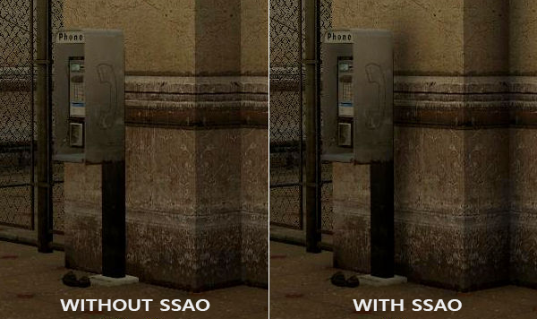
Below is an example image of a scene with and without ambient occlusion. Notice how especially between the creases, the (ambient) light is more occluded:
下面是有和没有环境光遮蔽的场景示例图。请注意,尤其是在拐角处,(环境)光被遮挡得更多:
While not an incredibly obvious effect, the image with ambient occlusion enabled does feel a lot more realistic due to these small occlusion-like details, giving the entire scene a greater feel of depth.
虽然效果并不明显,但由于这些类似遮挡的小细节,启用环境光遮蔽的图像确实感觉更加逼真,给整个场景带来了更强的深度感。
Ambient occlusion techniques are expensive as they have to take surrounding geometry into account. One could shoot a large number of rays for each point in space to determine its amount of occlusion, but that quickly becomes computationally infeasible for real-time solutions. In 2007, Crytek published a technique called screen-space ambient occlusion (SSAO) for use in their title Crysis. The technique uses a scene’s depth buffer in screen-space to determine the amount of occlusion instead of real geometrical data. This approach is incredibly fast compared to real ambient occlusion and gives plausible results, making it the de-facto standard for approximating real-time ambient occlusion.
环境光遮蔽技术成本高昂,因为它必须将周围的几何形状考虑在内。人们可以为空间中的每个点发射大量光线来确定其遮挡量,但对于实时方案来说,这种方法在计算上很快就变得不可行了。2007 年,Crytek 发布了一种称为屏幕空间环境光遮蔽 (SSAO) 的技术,并用在了他们的看家作《孤岛危机》上。该技术使用屏幕空间中场景的深度缓冲区来确定遮挡量,而不是实际的几何数据。与真正的环境光遮蔽相比,这种方法的速度非常快,并且给出了貌似真实的结果,使其在当时事实上成为了近似实时环境光遮蔽的标准。
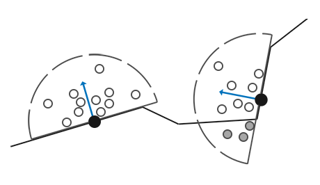
The basics behind screen-space ambient occlusion are simple: for each fragment on a screen-filled quad we calculate an occlusion factor based on the fragment’s surrounding depth values. The occlusion factor is then used to reduce or nullify the fragment’s ambient lighting component. The occlusion factor is obtained by taking multiple depth samples in a sphere sample kernel surrounding the fragment position and compare each of the samples with the current fragment’s depth value. The number of samples that have a higher depth value than the fragment’s depth represents the occlusion factor.
屏幕空间环境光遮蔽背后的基本原理很简单:对于填充屏幕的四边形上的每个片段,我们根据片段周围的深度值计算一个遮挡因子。然后使用这个遮挡因子来减少或消除片段的环境光照分量。遮挡因子是通过在片段位置周围的球形样本核中获取多个深度样本,并将每个样本与当前片段的深度值进行比较来获得的。将样本深度和片段深度相比较,具有更高深度值的样本的个数即就是遮挡因子。
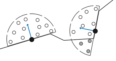
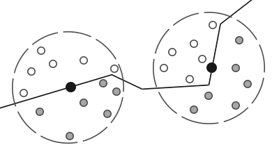 黑色点是当前正在进行遮蔽效果计算的片段,白色样本是对观察者可见的样本,灰色样本是对观察者不可见的样本。白色样本越多说明片段周围越空旷;黑色样本越多说明片段周围遮挡越多
Each of the gray depth samples that are inside geometry contribute to the total occlusion factor; the more samples we find inside geometry, the less ambient lighting the fragment should eventually receive.
上图中,几何体内部的每个灰色深度样本都对总遮挡因子有贡献;我们在几何体内发现的灰色样本越多,片段最终接收到的环境光就越少。
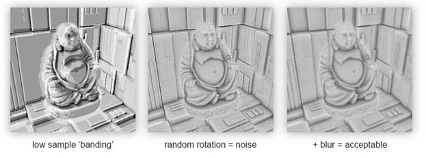
It is clear the quality and precision of the effect directly relates to the number of surrounding samples we take. If the sample count is too low, the precision drastically reduces and we get an artifact called banding; if it is too high, we lose performance. We can reduce the amount of samples we have to test by introducing some randomness into the sample kernel. By randomly rotating the sample kernel each fragment we can get high quality results with a much smaller amount of samples. This does come at a price as the randomness introduces a noticeable noise pattern that we’ll have to fix by blurring the results. Below is an image (courtesy of John Chapman) showcasing the banding effect and the effect randomness has on the results:
很明显,效果的质量和精度与我们采集的周围样本数量直接相关。如果样本数量太少,精度会大大降低,画面上会呈现出一种称为条带的加工痕迹;如果它太多,则会损失一定的性能。我们可以通过在样本核中引入一些随机性来减少必须测试的样本数量。通过随机旋转每个片段的样本核,我们可以用更少的样本获得高质量的结果。这确实是有代价的,因为随机性引入了明显的噪声图案,我们必须通过对结果进行模糊来进一步修复。下面是一张图片(由John Chapman提供),展示了条带效果以及随机性对结果的影响:
As you can see, even though we get noticeable banding on the SSAO results due to a low sample count, by introducing some randomness the banding effects are completely gone.
正如你所看到的,由于减少了样本数量,即使 SSAO 结果上出现了明显的条带,但通过引入一些随机性,条带效果完全消失了。
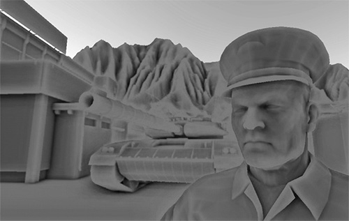
The SSAO method developed by Crytek had a certain visual style. Because the sample kernel used was a sphere, it caused flat walls to look gray as half of the kernel samples end up being in the surrounding geometry. Below is an image of Crysis’s screen-space ambient occlusion that clearly portrays this gray feel:
Crytek开发的SSAO方法有一个特定的视觉风格。因为使用的样本核是一个球体,核内一半的样本最终是在周围的几何体里,它会导致平坦的墙壁看起来是灰色的。下面是《孤岛危机》的屏幕空间环境光遮蔽图像,清楚地描绘了这种灰色的感觉(平坦墙壁墙面的中间显示为深灰色,带有环境光遮蔽的效果,其实是不应该有的,因为墙面的中间部位四周并没有被遮挡):
For that reason we won’t be using a sphere sample kernel, but rather a hemisphere sample kernel oriented along a surface’s normal vector.
因此,我们不会使用球形样本核,而是用一个半球样本核,这个半球样本核朝向表面的法向量方向。
By sampling around this normal-oriented hemisphere we do not consider the fragment’s underlying geometry to be a contribution to the occlusion factor. This removes the gray-feel of ambient occlusion and generally produces more realistic results. This chapter’s technique is based on this normal-oriented hemisphere method and a slightly modified version of John Chapman’s brilliant SSAO tutorial.
通过围绕这个法向半球进行采样,片段底部的几何体对遮挡因子就不会有影响。这消除了环境光遮蔽的灰色感,通常会产生更真实的结果。本章的技术基于这种法向半球方法,以及 John Chapman 出色的 SSAO 教程的略微修改版本。
Sample buffers
SSAO requires geometrical info as we need some way to determine the occlusion factor of a fragment. For each fragment, we’re going to need the following data:
SSAO 需要一些几何信息,用于确定片段的遮挡因子。对于每个片段,我们将需要以下数据:
- A per-fragment position vector.
- A per-fragment normal vector.
- A per-fragment albedo color.
- A sample kernel.
- A per-fragment random rotation vector used to rotate the sample kernel.
Using a per-fragment view-space position we can orient a sample hemisphere kernel around the fragment’s view-space surface normal and use this kernel to sample the position buffer texture at varying offsets. For each per-fragment kernel sample we compare its depth with its depth in the position buffer to determine the amount of occlusion. The resulting occlusion factor is then used to limit the final ambient lighting component. By also including a per-fragment rotation vector we can significantly reduce the number of samples we’ll need to take as we’ll soon see.
使用一个每片段的视图空间位置,根据这个片段的视图空间表面法线,我们可以确定半球样本核的位置和朝向,并使用这个核在不同偏移上去采样位置缓冲纹理。对于每片段的每个核样本,我们将其深度与其在位置缓冲区中的深度进行比较,以确定遮挡量。然后使用生成的遮挡因子来限制最终的环境光照分量。下面很快就会看到,通过进一步使用每个片段的旋转向量,我们可以显著减少需要采集的样本数量。
As SSAO is a screen-space technique we calculate its effect on each fragment on a screen-filled 2D quad. This does mean we have no geometrical information of the scene. What we could do, is render the geometrical per-fragment data into screen-space textures that we then later send to the SSAO shader so we have access to the per-fragment geometrical data. If you’ve followed along with the previous chapter you’ll realize this looks quite like a deferred renderer’s G-buffer setup. For that reason SSAO is perfectly suited in combination with deferred rendering as we already have the position and normal vectors in the G-buffer.
由于 SSAO 是一种屏幕空间技术,因此我们要计算它对填充屏幕的 2D 四边形上每个片段的影响。这确实意味着我们在计算时没有场景的几何信息。我们可以做的是将每个片段的几何数据渲染为屏幕空间纹理,然后将其发送到 SSAO 着色器,以便我们可以访问每个片段的几何数据。如果你已经学习了上一章的内容,你会发现这看起来很像延迟渲染器的 G-buffer 设置。因此,SSAO 非常适合与延迟渲染结合使用,因为延迟渲染已经在 G-buffer 中存储了位置和法向量。
As we should have per-fragment position and normal data available from the scene objects, the fragment shader of the geometry stage is fairly simple:
因为我们应该从场景对象中获得每个片段的位置和法线数据,所以几何阶段的片段着色器相当简单:
1
2
3
4
5
6
7
8
9
10
11
12
13
14
15
16
17
18
#version 330 core
layout (location = 0) out vec4 gPosition;
layout (location = 1) out vec3 gNormal;
layout (location = 2) out vec4 gAlbedoSpec;

in vec2 TexCoords;
in vec3 FragPos;
in vec3 Normal;

void main()
{
    // store the fragment position vector in the first gbuffer texture
    gPosition = FragPos;
    // also store the per-fragment normals into the gbuffer
    gNormal = normalize(Normal);
    // and the diffuse per-fragment color, ignore specular
    gAlbedoSpec.rgb = vec3(0.95);
}
Since SSAO is a screen-space technique where occlusion is calculated from the visible view, it makes sense to implement the algorithm in view-space. Therefore, FragPos and Normal as supplied by the geometry stage’s vertex shader are transformed to view space (multiplied by the view matrix as well).
因为 SSAO 是一种屏幕空间技术,其中遮挡是从可见视图计算的,所以在视图空间中实现该算法才是有意义的。因此,由几何阶段顶点着色器提供的 FragPos 和 Normal 将被转换到视图空间(通过乘以视图矩阵)。
The gPosition color buffer texture is configured as follows:
gPosition 颜色缓冲区纹理配置如下:
1
2
3
4
5
6
7
glGenTextures(1, &gPosition);
glBindTexture(GL_TEXTURE_2D, gPosition);
glTexImage2D(GL_TEXTURE_2D, 0, GL_RGBA16F, SCR_WIDTH, SCR_HEIGHT, 0, GL_RGBA, GL_FLOAT, NULL);
glTexParameteri(GL_TEXTURE_2D, GL_TEXTURE_MIN_FILTER, GL_NEAREST);
glTexParameteri(GL_TEXTURE_2D, GL_TEXTURE_MAG_FILTER, GL_NEAREST);
glTexParameteri(GL_TEXTURE_2D, GL_TEXTURE_WRAP_S, GL_CLAMP_TO_EDGE);
glTexParameteri(GL_TEXTURE_2D, GL_TEXTURE_WRAP_T, GL_CLAMP_TO_EDGE);
This gives us a position texture that we can use to obtain depth values for each of the kernel samples. Note that we store the positions in a floating point data format; this way position values aren’t clamped to [0.0,1.0] and we need the higher precision. Also note the texture wrapping method of GL_CLAMP_TO_EDGE. This ensures we don’t accidentally oversample position/depth values in screen-space outside the texture’s default coordinate region.
这为我们提供了一个位置纹理,我们可以使用它来获取每个核样本的深度值。请注意,我们以浮点数据格式存储位置;这样,位置值就不会被固定在 [ 0.0, 1.0 ] 范围,因为我们需要更高的精度。还要注意 GL_CLAMP_TO_EDGE 的纹理环绕方式。这样可以确保我们在意外的情况下采样到纹理默认坐标区域之外屏幕空间中时,位置/深度值不会过采样。
Next, we need the actual hemisphere sample kernel and some method to randomly rotate it.
接下来,我们需要实际的半球状样本核和一些随机旋转它的方法。
Normal-oriented hemisphere
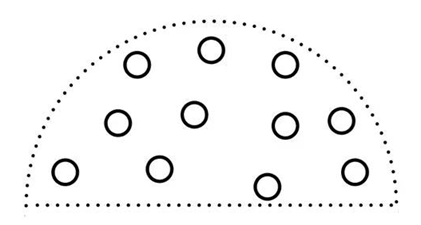
We need to generate a number of samples oriented along the normal of a surface. As we briefly discussed at the start of this chapter, we want to generate samples that form a hemisphere.
我们需要沿表面法线方向生成许多的样本。正如我们在本章开头简要讨论的那样,我们希望生成的样本呈半球状。
As it is difficult nor plausible to generate a sample kernel for each surface normal direction, we’re going to generate a sample kernel in tangent space, with the normal vector pointing in the positive z direction. Assuming we have a unit hemisphere, we can obtain a sample kernel with a maximum of 64 sample values as follows:
由于为每个表面法线方向生成一个样本核既困难也不合理,因此我们将在切线空间中生成一个样本核,切线空间中法向量指向正 z 方向。假设我们有一个单位半球,我们可以得到如下一个最大 64 样本数的样本核:
1
2
3
4
5
6
7
8
9
10
11
12
13
14
15
16
17
18
19
20
std::uniform_real_distribution<float> randomFloats(0.0, 1.0); // random floats between [0.0, 1.0]
std::default_random_engine generator;
std::vector<glm::vec3> ssaoKernel;
for (unsigned int i = 0; i < 64; ++i)
{
    // 在立方体正 z 轴一侧任取一点
    glm::vec3 sample(
        randomFloats(generator) * 2.0 - 1.0,
        randomFloats(generator) * 2.0 - 1.0,
        randomFloats(generator)
    );

    // 将样本归一化到单位半球表面
    sample  = glm::normalize(sample);

    // 将样本随机到单位半球内部
    sample *= randomFloats(generator);

    ssaoKernel.push_back(sample);
}
We vary the x and y direction in tangent space between -1.0 and 1.0, and vary the z direction of the samples between 0.0 and 1.0 (if we varied the z direction between -1.0 and 1.0 as well we’d have a sphere sample kernel). As the sample kernel will be oriented along the surface normal, the resulting sample vectors will all end up in the hemisphere.
我们在切线空间中变换 x 和 y 范围到 -1.0 和 1.0 之间,并变换样本的 z 范围到 0.0 和 1.0 之间(如果我们变换 z 范围到 -1.0 和 1.0 之间,我们将得到一个球形样本核)。由于样本核将沿表面法线定向,因此生成的样本向量最终将全部在半球内。
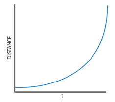
Currently, all samples are randomly distributed in the sample kernel, but we’d rather place a larger weight on occlusions close to the actual fragment. We want to distribute more kernel samples closer to the origin. We can do this with an accelerating interpolation function:
现在,所有样本都是随机分布在样本核中的,但我们更愿意在靠近实际片段的遮挡上放置更大的权重。我们希望在更接近原点的地方分布更多的核样本。可以通过加速插值函数来做到这一点:
1
2
3
4
   float scale = (float)i / 64.0;             // scale 值范围是 [0, 1)
   scale   = lerp(0.1f, 1.0f, scale * scale); // 插值权重使用 scale * scale 形式的指数抛物线,相比于直接使用 scale 形式的线性权重,在[0, 1)的取值范围内,使得更多次插值取值后获取的 scale 更靠近 0.1
   sample *= scale;                           // sample 本身是单位半球内的样本,再使用 scale 缩放后,长度更小,更靠近片段了
   ssaoKernel.push_back(sample);
Where lerp(linear interpolation) is defined as:
其中 lerp(线性插值) 定义为:
1
2
3
4
float lerp(float a, float b, float f)
{
    return a + f * (b - a); // (1 - f) * a + f * b
}
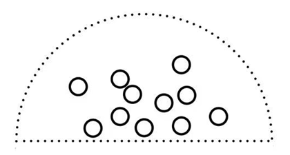
This gives us a kernel distribution that places most samples closer to its origin.
这为我们提供了一个使大多数样本更接近其原点的核分布。
Each of the kernel samples will be used to offset the view-space fragment position to sample surrounding geometry.
每个核样本将用于偏移视图空间片段位置,以对周围的几何体进行采样。将带权重的样本核应用到表面将会是如下图所示效果:
We do need quite a lot of samples in view-space in order to get realistic results, which may be too heavy on performance. However, if we can introduce some semi-random rotation/noise on a per-fragment basis, we can significantly reduce the number of samples required.
为了获得逼真的结果,我们确实需要在视图空间中提供相当多的样本,这可能对性能的影响很大。但是,如果我们可以在每个片段的基础上引入一些半随机旋转/噪声,我们可以显著减少所需的样本数量。
Random kernel rotations
By introducing some randomness onto the sample kernels we largely reduce the number of samples necessary to get good results. We could create a random rotation vector for each fragment of a scene, but that quickly eats up memory. It makes more sense to create a small texture of random rotation vectors that we tile over the screen.
通过在样本核上引入一些随机性,我们可以在很大程度上减少获得良好结果所需的样本数量。我们可以为场景的每个片段创建一个随机旋转向量,但这很快就会吃光内存。创建一小块随机旋转矢量纹理,并将其(以瓦片的形式重复地)平铺在屏幕上更有意义。
We create a 4x4 array of random rotation vectors oriented around the tangent-space surface normal:
我们创建一个 4x4 的随机旋转向量数组,随机旋转向量的朝向围绕着切线空间表面法线:
1
2
3
4
5
6
7
8
9
std::vector<glm::vec3> ssaoNoise;
for (unsigned int i = 0; i < 16; i++)
{
    glm::vec3 noise(
        randomFloats(generator) * 2.0 - 1.0,
        randomFloats(generator) * 2.0 - 1.0,
        0.0f);
    ssaoNoise.push_back(noise);
}
As the sample kernel is oriented along the positive z direction in tangent space, we leave the z component at 0.0 so we rotate around the z axis.
当样本核的朝向沿切线空间中正 z 方向时,我们设定 z 分量为 0.0 ,以便绕 z 轴旋转。
We then create a 4x4 texture that holds the random rotation vectors; make sure to set its wrapping method to GL_REPEAT so it properly tiles over the screen.
然后,我们创建一个 4x4 纹理来保存随机旋转向量;确保将其环绕方式设置为 GL_REPEAT,以便它正确地平铺在屏幕上(将一个 4x4 纹理瓦片重复地铺满整个屏幕)。
1
2
3
4
5
6
7
8
unsigned int noiseTexture;
glGenTextures(1, &noiseTexture);
glBindTexture(GL_TEXTURE_2D, noiseTexture);
glTexImage2D(GL_TEXTURE_2D, 0, GL_RGBA16F, 4, 4, 0, GL_RGB, GL_FLOAT, &ssaoNoise[0]);
glTexParameteri(GL_TEXTURE_2D, GL_TEXTURE_MIN_FILTER, GL_NEAREST);
glTexParameteri(GL_TEXTURE_2D, GL_TEXTURE_MAG_FILTER, GL_NEAREST);
glTexParameteri(GL_TEXTURE_2D, GL_TEXTURE_WRAP_S, GL_REPEAT);
glTexParameteri(GL_TEXTURE_2D, GL_TEXTURE_WRAP_T, GL_REPEAT);
We now have all the relevant input data we need to implement SSAO.
现在,我们拥有了实现 SSAO 所需的所有相关输入数据。
The SSAO shader
The SSAO shader runs on a 2D screen-filled quad that calculates the occlusion value for each of its fragments. As we need to store the result of the SSAO stage (for use in the final lighting shader), we create yet another framebuffer object:
SSAO 着色器运行在一个 2D 填充屏幕的四边形上,该四边形计算其每个片段的遮挡值。由于我们需要存储 SSAO 阶段的结果(用于最终的光照着色器),因此我们创建了另一个帧缓冲对象:
1
2
3
4
5
6
7
8
9
10
11
12
unsigned int ssaoFBO;
glGenFramebuffers(1, &ssaoFBO);
glBindFramebuffer(GL_FRAMEBUFFER, ssaoFBO);

unsigned int ssaoColorBuffer;
glGenTextures(1, &ssaoColorBuffer);
glBindTexture(GL_TEXTURE_2D, ssaoColorBuffer);
glTexImage2D(GL_TEXTURE_2D, 0, GL_RED, SCR_WIDTH, SCR_HEIGHT, 0, GL_RED, GL_FLOAT, NULL);
glTexParameteri(GL_TEXTURE_2D, GL_TEXTURE_MIN_FILTER, GL_NEAREST);
glTexParameteri(GL_TEXTURE_2D, GL_TEXTURE_MAG_FILTER, GL_NEAREST);

glFramebufferTexture2D(GL_FRAMEBUFFER, GL_COLOR_ATTACHMENT0, GL_TEXTURE_2D, ssaoColorBuffer, 0);
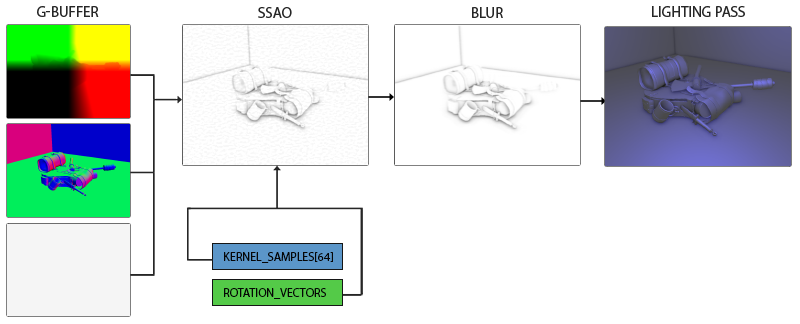
As the ambient occlusion result is a single grayscale value we’ll only need a texture’s red component, so we set the color buffer’s internal format to GL_RED.
由于环境光遮蔽结果是单个灰度值,我们只需要纹理的红色分量,因此我们将颜色缓冲区的内部格式设置为 GL_RED。
The complete process for rendering SSAO then looks a bit like this:
渲染 SSAO 的完整过程看起来有点像这样:
1
2
3
4
5
6
7
8
9
10
11
12
13
14
15
16
17
18
19
20
21
22
23
24
25
26
27
28
// geometry pass: render stuff into G-buffer
glBindFramebuffer(GL_FRAMEBUFFER, gBuffer);
    [...]
glBindFramebuffer(GL_FRAMEBUFFER, 0);

// use G-buffer to render SSAO texture
glBindFramebuffer(GL_FRAMEBUFFER, ssaoFBO);
    glClear(GL_COLOR_BUFFER_BIT);
    glActiveTexture(GL_TEXTURE0);
    glBindTexture(GL_TEXTURE_2D, gPosition);
    glActiveTexture(GL_TEXTURE1);
    glBindTexture(GL_TEXTURE_2D, gNormal);
    glActiveTexture(GL_TEXTURE2);
    glBindTexture(GL_TEXTURE_2D, noiseTexture);
    shaderSSAO.use();
    SendKernelSamplesToShader();
    shaderSSAO.setMat4("projection", projection);
    RenderQuad();
glBindFramebuffer(GL_FRAMEBUFFER, 0);

// lighting pass: render scene lighting
glClear(GL_COLOR_BUFFER_BIT | GL_DEPTH_BUFFER_BIT);
shaderLightingPass.use();
[...]
glActiveTexture(GL_TEXTURE3);
glBindTexture(GL_TEXTURE_2D, ssaoColorBuffer);
[...]
RenderQuad();
The shaderSSAO shader takes as input the relevant G-buffer textures, the noise texture, and the normal-oriented hemisphere kernel samples:
shaderSSAO 着色器将相关的 G-buffer 纹理、噪声纹理和法向半球核样本作为输入:
1
2
3
4
5
6
7
8
9
10
11
12
13
14
15
16
17
18
19
#version 330 core
out float FragColor;

in vec2 TexCoords;

uniform sampler2D gPosition;
uniform sampler2D gNormal;
uniform sampler2D texNoise;

uniform vec3 samples[64];
uniform mat4 projection;

// tile noise texture over screen, based on screen dimensions divided by noise size
const vec2 noiseScale = vec2(800.0/4.0, 600.0/4.0); // screen = 800x600

void main()
{
    [...]
}
Interesting to note here is the noiseScale variable. We want to tile the noise texture all over the screen, but as the TexCoords vary between 0.0 and 1.0, the texNoise texture won’t tile at all. So we’ll calculate the required amount to scale TexCoords by dividing the screen’s dimensions by the noise texture size.
这里需要注意的是 noiseScale 变量。我们想在整个屏幕上铺满之前创建的 4x4 噪声纹理瓦片,但由于 TexCoords 在 0.0 和 1.0 之间变化,texNoise 纹理根本不会被按这样的预想方式平铺开来。因此,我们通过将屏幕的尺寸除以噪声纹理尺寸来计算所需的 TexCoords 缩放量。
1
2
3
vec3 fragPos   = texture(gPosition, TexCoords).xyz;             // 片段在视图空间中的位置
vec3 normal    = texture(gNormal, TexCoords).rgb;               // 片段在视图空间中的法线
vec3 randomVec = texture(texNoise, TexCoords * noiseScale).xyz;
As we set the tiling parameters of texNoise to GL_REPEAT, the random values will be repeated all over the screen. Together with the fragPos and normal vector, we then have enough data to create a TBN matrix that transforms any vector from tangent-space to view-space:
当我们将 texNoise 的平铺参数设置为 GL_REPEAT 时,随机值将在整个屏幕上重复出现。结合 fragPos 和法向量,我们现在有足够的数据来创建一个 TBN 矩阵了,该矩阵将任何向量从切线空间转换为视图空间:
1
2
3
vec3 tangent   = normalize(randomVec - normal * dot(randomVec, normal));
vec3 bitangent = cross(normal, tangent);
mat3 TBN       = mat3(tangent, bitangent, normal);
Using a process called the Gramm-Schmidt process we create an orthogonal basis, each time slightly tilted based on the value of randomVec. Note that because we use a random vector for constructing the tangent vector, there is no need to have the TBN matrix exactly aligned to the geometry’s surface, thus no need for per-vertex tangent (and bitangent) vectors.
使用一种称为 Gramm-Schmidt 处理的过程,我们创建了一个正交基,并根据 randomVec 的值进行了略微倾斜。请注意,由于我们使用随机向量来构造切向量,在这里不需要将 TBN 矩阵与几何图形的表面精确对齐,因此不需要每个顶点的正切(和副切)向量。
对于切向量的计算,这里解释下计算过程:因为 normal 为单位法向量,randomVec 和 normal 点积(即 dot(randomVec, normal))给出了 randomVec 在 normal 方向上的投影长度。然后,我们将这个投影长度乘以 normal 向量(即 normal * dot(randomVec, normal)),得到 randomVec 在 normal 方向上的分量。从 randomVec 中减去这个分量,我们就得到了一个新的向量,它与 normal 向量垂直,这一步我们实际上是在消除 randomVec 中与 normal 平行的部分,从而得到一个与 normal 垂直的向量,因为 randomVec 可以分解为平行于 normal 的分量 h_randomVec 和垂直于 normal 的分量 v_randomVec,即 randomVec = h_randomVec + v_randomVec。
Next we iterate over each of the kernel samples, transform the samples from tangent to view-space, add them to the current fragment position, and compare the fragment position’s depth with the sample depth stored in the view-space position buffer. Let’s discuss this in a step-by-step fashion:
接下来,我们遍历每个核样本,将样本从切线空间转换为视图空间,将它们加到当前片段位置上,并将片段位置的深度与存储在视图空间位置缓冲中的样本深度进行比较。让我们一步一步地讨论这个问题:
1
2
3
4
5
6
7
8
9
float occlusion = 0.0;
for(int i = 0; i < kernelSize; ++i)
{
    // get sample position
    vec3 samplePos = TBN * samples[i]; // from tangent to view-space
    samplePos = fragPos + samplePos * radius;

    [...]
}
Here kernelSize and radius are variables that we can use to tweak the effect; in this case a value of 64 and 0.5 respectively. For each iteration we first transform the respective sample to view-space. We then add the view-space kernel offset sample to the view-space fragment position. Then we multiply the offset sample by radius to increase (or decrease) the effective sample radius of SSAO.
这里 kernelSize 和 radius 是我们可以用来调整效果的变量;在本例中,值分别为 64 和 0.5。对于每次迭代,首先我们将相应的样本转换到视图空间。然后,我们将偏移样本乘以 radius 以增加(或减少)SSAO 的有效样本半径。再然后,我们将视图空间核偏移样本添加到视图空间片段位置上。
Next we want to transform sample to screen-space so we can sample the position/depth value of sample as if we were rendering its position directly to the screen. As the vector is currently in view-space, we’ll transform it to clip-space first using the projection matrix uniform:
接下来,我们要将样本转换到屏幕空间,以便我们可以对(位置缓冲纹理中)样本(对应)的位置/深度值进行采样,就好像我们将其位置直接渲染到屏幕上一样。由于向量当前位于视图空间中,我们将首先使用投影矩阵 uniform 将其转换到裁剪空间:
1
2
3
4
vec4 offset = vec4(samplePos, 1.0);
offset      = projection * offset;    // from view to clip-space
offset.xyz /= offset.w;               // perspective divide
offset.xyz  = offset.xyz * 0.5 + 0.5; // transform to range 0.0 - 1.0
After the variable is transformed to clip-space, we perform the perspective divide step by dividing its xyz components with its w component. The resulting normalized device coordinates are then transformed to the [0.0, 1.0] range so we can use them to sample the position texture:
将变量转换到裁剪空间后,我们通过将其 xyz 分量与其 w 分量相除来执行透视除法步骤。然后将生成的标准化设备坐标转换到 [0.0, 1.0] 范围,以便我们可以使用它们对位置纹理进行采样:
1
float sampleDepth = texture(gPosition, offset.xy).z;
We use the offset vector’s x and y component to sample the position texture to retrieve the depth (or z value) of the sample position as seen from the viewer’s perspective (the first non-occluded visible fragment). We then check if the sample’s current depth value is larger than the stored depth value and if so, we add to the final contribution factor:
我们使用偏移向量的 x 和 y 分量对位置纹理进行采样,以获取从观察者视角看到的样本位置的深度(或 z 值)(第一个未被遮挡的可见片段)。然后,我们检查样本的当前深度值是否大于存储的深度值,如果是,则添加到最终贡献因子中:
1
2
3
4
5
6
7
8
9
10
11
12
13
// 判断样本有没有被遮挡
// 如果 sampleDepth 大于或等于 sample.z + bias,则认为样本点没有被遮挡,返回 1.0;否则,认为样本点被遮挡,返回 0.0。
occlusion += (sampleDepth >= samplePos.z + bias ? 1.0 : 0.0);
//            -----------    -----------
//                ||             ||
//                ||             \/
//                ||            样本点
//                ||       在视图空间中的深度
//                \/
//          样本点对应在屏幕上
//          那个最靠近观察者的
//           第一个可见片段
//          在视图空间中的深度
OpenGL 视图空间坐标被定义在右手坐标系系统中,X 轴向右,Y 轴向上,Z 轴朝屏幕外。摄像机位于原点(0,0,0)并始终看向 -Z 轴。这里深度和 Z 值呈反向关系,因此离相机越远深度越大获取的 Z 值越小,离相机越近深度越小获取的 Z 值越大。sampleDepth 和 samplePos.z 都是负值,sampleDepth 值大于等于 samplePos.z,说明样本对应在屏幕上的可见片段深度小于样本点深度(也就是上文说的当前样本深度值大于存储的深度值意思),离相机更近,对于样本点形成了遮挡。
Note that we add a small bias here to the original fragment’s depth value (set to 0.025 in this example). A bias isn’t always necessary, but it helps visually tweak the SSAO effect and solves acne effects that may occur based on the scene’s complexity.
请注意,我们在原始片段的深度值中添加了一个小小的 bias 值(在此示例中设置为 0.025 )。偏置并不总是必要的,但它有助于在视觉上调整 SSAO 效果,并解决根据场景复杂度可能发生的失真效果。
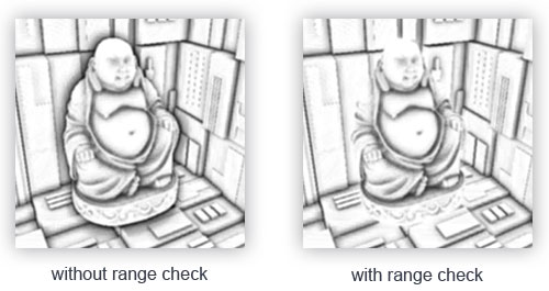
We’re not completely finished yet as there is still a small issue we have to take into account. Whenever a fragment is tested for ambient occlusion that is aligned close to the edge of a surface, it will also consider depth values of surfaces far behind the test surface; these values will (incorrectly) contribute to the occlusion factor. We can solve this by introducing a range check as the following image (courtesy of John Chapman) illustrates:
到目前为止还没有完全完成,因为还有一个小问题我们必须要考虑。每当为环境光遮蔽测试靠近表面边缘的片段时,它还会将远在测试片段后面的表面的深度值考虑在内(以下面左侧图片为例说明,这会导致佛像边缘和后面墙壁间产生环境光遮蔽效果,但其实佛像和后面墙壁距离还很远,它们之间没有这么明显的影响);这些值将(错误地)影响遮挡因子。我们可以通过引入范围检查来解决这个问题,如下图所示(由 John Chapman 提供):
We introduce a range check that makes sure a fragment contributes to the occlusion factor if its depth values is within the sample’s radius. We change the last line to:
我们引入了一个范围检查,以确保如果片段的深度值是在样本的半径范围内,则片段对遮挡因子有贡献。我们将最后一行更改为:
1
2
3
4
// 当前片段和样本点对应在屏幕上可见片段之间深度差越大,离的就越远,遮蔽影响越小,
// rangeCheck 越趋近于 0,遮挡权重就越小
float rangeCheck = smoothstep(0.0, 1.0, radius / abs(fragPos.z - sampleDepth));
occlusion       += (sampleDepth >= samplePos.z + bias ? 1.0 : 0.0) * rangeCheck;
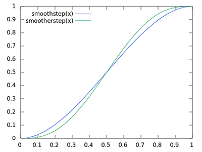
Here we used GLSL’s smoothstep function that smoothly interpolates its third parameter between the first and second parameter’s range, returning 0.0 if less than or equal to its first parameter and 1.0 if equal or higher to its second parameter. If the depth difference ends up between radius, its value gets smoothly interpolated between 0.0 and 1.0 by the following curve:
在这里,我们使用了 GLSL 的 smoothstep 函数,该函数根据其第三个参数在第一个和第二个参数之间平滑地插值,如果小于或等于其第一个参数返回 0.0,如果等于或大于其第二个参数返回 1.0。如果深度差最终在 radius 之内,则其值将按照以下曲线在 0.0 和 1.0 之间平滑插值:
If we were to use a hard cut-off range check that would abruptly remove occlusion contributions if the depth values are outside radius, we’d see obvious (unattractive) borders at where the range check is applied.
如果我们要使用硬截断范围检查,当深度值在半径之外时,将突然移除遮挡贡献,我们会在应用范围检查的地方看到明显的(令人不愉快的)边界。
As a final step we normalize the occlusion contribution by the size of the kernel and output the results. Note that we subtract the occlusion factor from 1.0 so we can directly use the occlusion factor to scale the ambient lighting component.
最后一步,我们使用核的大小对遮挡贡献进行归一化,并输出结果。请注意,我们从 1.0 中减去遮挡因子,以便我们可以直接使用遮挡因子来缩放环境光照项。
1
2
occlusion = 1.0 - (occlusion / kernelSize);
FragColor = occlusion;
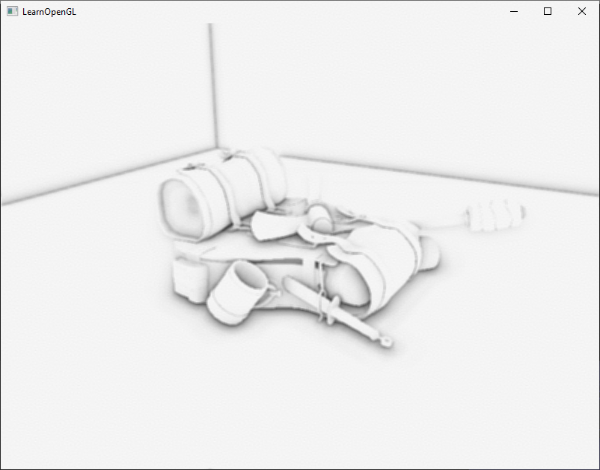
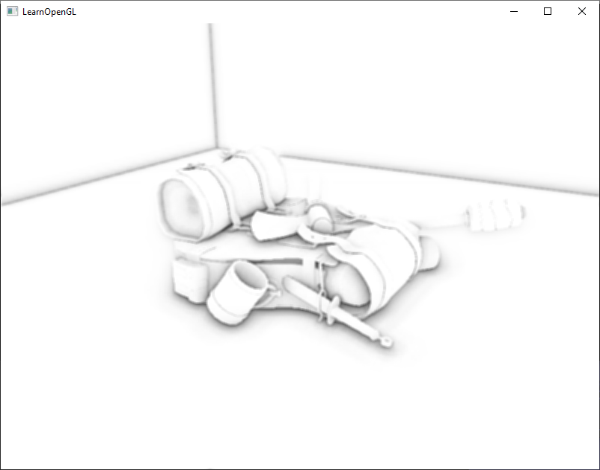
If we’d imagine a scene where our favorite backpack model is taking a little nap, the ambient occlusion shader produces the following texture:
如果我们想象一个静置背包的场景,环境光遮蔽着色器会生成下面的纹理:
As we can see, ambient occlusion gives a great sense of depth. With just the ambient occlusion texture we can already clearly see the model is indeed laying on the floor, instead of hovering slightly above it.
正如我们所看到的,环境光遮蔽给人一种很好的深度感。仅通过环境光遮蔽纹理,我们已经可以清楚地看到模型确实躺在地板上,而不是轻轻漂浮在地板上。
It still doesn’t look perfect, as the repeating pattern of the noise texture is clearly visible. To create a smooth ambient occlusion result we need to blur the ambient occlusion texture.
这看起来仍不完美,因为使用重复噪声纹理的模式,不平滑的遮蔽效果清晰可见。为了创建平滑的环境光遮蔽结果,我们需要对环境光遮蔽纹理进行模糊。
Ambient occlusion blur
Between the SSAO pass and the lighting pass, we first want to blur the SSAO texture. So let’s create yet another framebuffer object for storing the blur result:
在 SSAO 通道和 lighting 通道之间,我们还要对 SSAO 纹理进行模糊。因此,让我们创建另一个用于存储模糊结果的帧缓冲对象:
1
2
3
4
5
6
7
8
9
unsigned int ssaoBlurFBO, ssaoColorBufferBlur;
glGenFramebuffers(1, &ssaoBlurFBO);
glBindFramebuffer(GL_FRAMEBUFFER, ssaoBlurFBO);
glGenTextures(1, &ssaoColorBufferBlur);
glBindTexture(GL_TEXTURE_2D, ssaoColorBufferBlur);
glTexImage2D(GL_TEXTURE_2D, 0, GL_RED, SCR_WIDTH, SCR_HEIGHT, 0, GL_RED, GL_FLOAT, NULL);
glTexParameteri(GL_TEXTURE_2D, GL_TEXTURE_MIN_FILTER, GL_NEAREST);
glTexParameteri(GL_TEXTURE_2D, GL_TEXTURE_MAG_FILTER, GL_NEAREST);
glFramebufferTexture2D(GL_FRAMEBUFFER, GL_COLOR_ATTACHMENT0, GL_TEXTURE_2D, ssaoColorBufferBlur, 0);
Because the tiled random vector texture gives us a consistent randomness, we can use this property to our advantage to create a simple blur shader:
由于平铺的是随机矢量纹理瓦片,这为我们提供了一致的随机性,因此我们可以利用此属性来创建简单的模糊着色器:
1
2
3
4
5
6
7
8
9
10
11
12
13
14
15
16
17
18
19
20
21
22
23
#version 330 core
out float FragColor;

in vec2 TexCoords;

uniform sampler2D ssaoInput;

void main() {
    //---------------------------------------------------------------
    // textureSize — retrieve the dimensions of a level of a texture
    //---------------------------------------------------------------
    vec2 texelSize = 1.0 / vec2(textureSize(ssaoInput, 0));
    float result = 0.0;
    for (int x = -2; x < 2; ++x)
    {
        for (int y = -2; y < 2; ++y)
        {
            vec2 offset = vec2(float(x), float(y)) * texelSize;
            result += texture(ssaoInput, TexCoords + offset).r;
        }
    }
    FragColor = result / (4.0 * 4.0);
}
Here we traverse the surrounding SSAO texels between -2.0 and 2.0, sampling the SSAO texture an amount identical to the noise texture’s dimensions. We offset each texture coordinate by the exact size of a single texel using textureSize that returns a vec2 of the given texture’s dimensions. We average the obtained results to get a simple, but effective blur:
这里,我们在 -2.0 和 2.0 之间遍历周围的 SSAO 纹素,采样 SSAO 纹理次数与噪声纹理的规模相同。我们使用 textureSize 将每个纹理坐标偏移单个纹素大小的确切倍数,textureSize 返回给定纹理的一个 vec2 类型尺寸。我们对获得的结果进行平均,以获得简单但有效的模糊:
And there we go, a texture with per-fragment ambient occlusion data; ready for use in the lighting pass.
这就是我们继续往下进行,准备在 lighting 通道中使用,包含了每个片段的环境光遮蔽数据的纹理。
Applying ambient occlusion
Applying the occlusion factors to the lighting equation is incredibly easy: all we have to do is multiply the per-fragment ambient occlusion factor to the lighting’s ambient component and we’re done. If we take the Blinn-Phong deferred lighting shader of the previous chapter and adjust it a bit, we get the following fragment shader:
将遮挡因子应用于光照方程非常容易:我们所要做的就是将每个片段的环境光遮蔽因子乘以光照的环境分量,然后就完成了。如果我们采用上一章的 Blinn-Phong 延迟光照着色器并对其进行一些调整,我们将得到以下片段着色器:
1
2
3
4
5
6
7
8
9
10
11
12
13
14
15
16
17
18
19
20
21
22
23
24
25
26
27
28
29
30
31
32
33
34
35
36
37
38
39
40
41
42
43
44
45
46
47
48
#version 330 core
out vec4 FragColor;

in vec2 TexCoords;

uniform sampler2D gPosition;
uniform sampler2D gNormal;
uniform sampler2D gAlbedo;
uniform sampler2D ssao;

struct Light {
    vec3 Position;
    vec3 Color;

    float Linear;
    float Quadratic;
    float Radius;
};
uniform Light light;

void main()
{
    // retrieve data from gbuffer
    vec3 FragPos = texture(gPosition, TexCoords).rgb;
    vec3 Normal = texture(gNormal, TexCoords).rgb;
    vec3 Diffuse = texture(gAlbedo, TexCoords).rgb;
    float AmbientOcclusion = texture(ssao, TexCoords).r;

    // blinn-phong (in view-space)
    vec3 ambient = vec3(0.3 * Diffuse * AmbientOcclusion); // here we add occlusion factor
    vec3 lighting  = ambient;
    vec3 viewDir  = normalize(-FragPos); // viewpos is (0.0.0) in view-space
    // diffuse
    vec3 lightDir = normalize(light.Position - FragPos);
    vec3 diffuse = max(dot(Normal, lightDir), 0.0) * Diffuse * light.Color;
    // specular
    vec3 halfwayDir = normalize(lightDir + viewDir);
    float spec = pow(max(dot(Normal, halfwayDir), 0.0), 8.0);
    vec3 specular = light.Color * spec;
    // attenuation
    float dist = length(light.Position - FragPos);
    float attenuation = 1.0 / (1.0 + light.Linear * dist + light.Quadratic * dist * dist);
    diffuse  *= attenuation;
    specular *= attenuation;
    lighting += diffuse + specular;

    FragColor = vec4(lighting, 1.0);
}
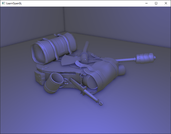
The only thing (aside from the change to view-space) we really changed is the multiplication of the scene’s ambient component by AmbientOcclusion. With a single blue-ish point light in the scene we’d get the following result:
我们唯一真正改变的(除了对观察空间的更改)是场景的环境分量现在乘以了 AmbientOcclusion。在场景中使用单个蓝色点光源时,我们将得到以下结果:
You can find the full source code of the demo scene here.
您可以在此处找到示例场景的完整源代码。
Screen-space ambient occlusion is a highly customizable effect that relies heavily on tweaking its parameters based on the type of scene. There is no perfect combination of parameters for every type of scene. Some scenes only work with a small radius, while other scenes require a larger radius and a larger sample count for them to look realistic. The current demo uses 64 samples, which is a bit much; play around with a smaller kernel size and try to get good results.
屏幕空间环境光遮蔽是一种可高度自定义的效果,它在很大程度上依赖于根据场景类型而进行的参数调整。对于每种类型的场景,没有完美的参数组合。一些场景仅在小半径时才表现的好,而另一些场景需要更大的半径和更大的样本数才能使它们看起来逼真。当前的示例使用了 64 个样本,这有点多;感兴趣的话可以尝试使用较小的核大小来获得好的结果。
Some parameters you can tweak (by using uniforms for example): kernel size, radius, bias, and/or the size of the noise kernel. You can also raise the final occlusion value to a user-defined power to increase its strength:
你可以调整一些参数(例如,通过使用 uniforms 设置 shader 中的参数值):核大小、半径、偏置、和/或噪声核的大小。你还可以将最终遮挡值提升到用户定义的幂上,以增加其强度:
1
2
occlusion = 1.0 - (occlusion / kernelSize);
FragColor = pow(occlusion, power);
Play around with different scenes and different parameters to appreciate the customizability of SSAO.
尝试不同的场景和不同的参数,以欣赏 SSAO 的可定制性。
Even though SSAO is a subtle effect that isn’t too clearly noticeable, it adds a great deal of realism to properly lit scenes and is definitely a technique you’d want to have in your toolkit.
尽管 SSAO 是一种不太明显的细微效果,但它为有适当光照的场景增加了大量的真实感,绝对是你希望塞进工具包中的一种技术。
