Deferred Shading
延迟着色是基于将大多数繁重的渲染(如光照)延迟或推迟到稍后的阶段中这样一种想法。延迟着色由两个通道组成:在第一个通道(称为几何通道)中,我们渲染一次场景,并获取对象的各种几何信息(例如位置向量、颜色向量、法线向量和/或镜面反射值),将其存储在称为 G-buffer 的纹理集合中。在称为光照通道的第二通道中使用 G-buffer 的纹理,在该通道中,我们渲染一个填充屏幕的四边形,并使用存储在 G-buffer 中的几何信息计算每个片段的场景光照(我们逐个像素地遍历 G-buffer)。
Introduction
The way we did lighting so far was called forward rendering or forward shading. A straightforward approach where we render an object and light it according to all light sources in a scene. We do this for every object individually for each object in the scene. While quite easy to understand and implement it is also quite heavy on performance as each rendered object has to iterate over each light source for every rendered fragment, which is a lot! Forward rendering also tends to waste a lot of fragment shader runs in scenes with a high depth complexity (multiple objects cover the same screen pixel) as fragment shader outputs are overwritten.
到目前为止,我们实现光照的方式被称为前向渲染或前向着色。它是一种非常直接的方式,我们渲染一个对象,并使用场景中的所有光源照亮它,然后为场景中的每个对象分别执行此操作。虽然很容易理解和实现,但它对性能的影响也相当大,因为每个渲染对象都必须为它的每个渲染片段迭代每个光源,这是非常多的!在深度复杂性高(多个对象覆盖同一屏幕像素)的场景中,正向渲染也往往会浪费大量可用的片段着色器资源,因为有些片段着色器输出会被覆盖。
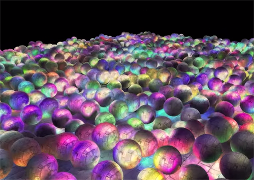
Deferred shading or deferred rendering aims to overcome these issues by drastically changing the way we render objects. This gives us several new options to significantly optimize scenes with large numbers of lights, allowing us to render hundreds (or even thousands) of lights with an acceptable framerate. The following image is a scene with 1847 point lights rendered with deferred shading (image courtesy of Hannes Nevalainen); something that wouldn’t be possible with forward rendering.
延迟着色或延迟渲染旨在通过彻底改变我们渲染对象的方式来克服这些问题。这为我们提供了几个新选项来显著优化具有大量光源的场景,使我们能够以可接受的帧速率渲染数百个(甚至数千个)光源。下图是使用延迟着色渲染 1847 个点光源的场景(图片由 Hannes Nevalainen 提供),这是前向渲染很难实现的。
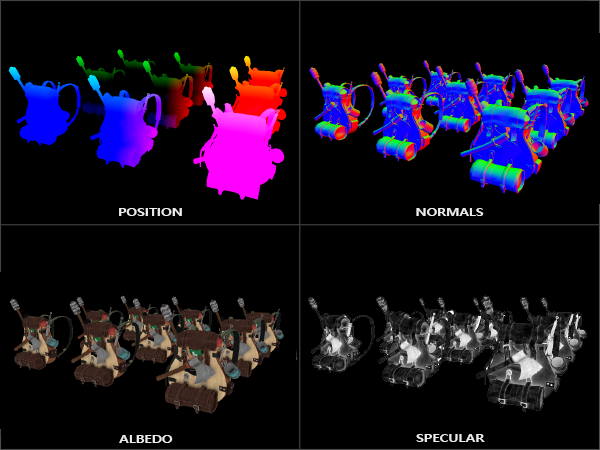
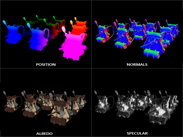
Deferred shading is based on the idea that we defer or postpone most of the heavy rendering (like lighting) to a later stage. Deferred shading consists of two passes: in the first pass, called the geometry pass, we render the scene once and retrieve all kinds of geometrical information from the objects that we store in a collection of textures called the G-buffer; think of position vectors, color vectors, normal vectors, and/or specular values. The geometric information of a scene stored in the G-buffer is then later used for (more complex) lighting calculations. Below is the content of a G-buffer of a single frame:
延迟着色是基于将大多数繁重的渲染(如光照)延迟或推迟到稍后的阶段中这样一种想法。延迟着色由两个通道组成:在第一个通道(称为几何通道)中,我们渲染一次场景,并获取对象的各种几何信息(例如位置向量、颜色向量、法线向量和/或镜面反射值),将其存储在称为 G-buffer 的纹理集合中。然后,存储在 G-buffer 中的场景几何信息稍后用于(更复杂的)光照计算。以下是单个帧的 G-buffer 的内容:
We use the textures from the G-buffer in a second pass called the lighting pass where we render a screen-filled quad and calculate the scene’s lighting for each fragment using the geometrical information stored in the G-buffer; pixel by pixel we iterate over the G-buffer. Instead of taking each object all the way from the vertex shader to the fragment shader, we decouple its advanced fragment processes to a later stage. The lighting calculations are exactly the same, but this time we take all required input variables from the corresponding G-buffer textures, instead of the vertex shader (plus some uniform variables).
我们在称为光照通道的第二通道中使用 G-buffer 的纹理,在该通道中,我们渲染一个填充屏幕的四边形,并使用存储在 G-buffer 中的几何信息计算每个片段的场景光照(我们逐个像素地遍历 G-buffer)。我们没有将每个对象从顶点着色器一路带到片段着色器,而是将其片段的高级处理解耦到后期阶段进行。光照计算过程和之前完全相同,只是这次我们不从顶点着色器(和一些 uniform 变量)中获取所有必需的输入变量,而是从相应的 G-buffer 纹理中获取。
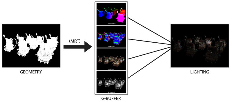
The image below nicely illustrates the process of deferred shading.
下图很好地说明了延迟着色的过程。
A major advantage of this approach is that whatever fragment ends up in the G-buffer is the actual fragment information that ends up as a screen pixel. The depth test already concluded this fragment to be the last and top-most fragment. This ensures that for each pixel we process in the lighting pass, we only calculate lighting once. Furthermore, deferred rendering opens up the possibility for further optimizations that allow us to render a much larger amount of light sources compared to forward rendering.
这种方法的一个主要优点是,无论 G-buffer 中记录了哪些片段信息,最终都会成为屏幕像素的实际片段信息。经过深度测试后,这个片段就是最后一个也是最前面的片段。这确保了在光照通道中,对于我们处理的每个像素,只会被计算一次光照。此外,延迟渲染为进一步优化提供了可能性,与前向渲染相比,我们可以渲染更多的光源。
It also comes with some disadvantages though as the G-buffer requires us to store a relatively large amount of scene data in its texture color buffers. This eats memory, especially since scene data like position vectors require a high precision. Another disadvantage is that it doesn’t support blending (as we only have information of the top-most fragment) and MSAA no longer works. There are several workarounds for this that we’ll get to at the end of the chapter.
不过,它也有一些缺点,因为 G-buffer 要求我们在其纹理颜色缓冲区中存储相对大量的场景数据。这会占用一些显存,尤其是类似位置向量之类的需要高精度的场景数据,消耗的显存更多。另一个缺点是它不支持混合(因为我们只有最前面片段的信息),并且 MSAA 不再有效。对于这些问题有几种解决方法,我们将在本章末尾介绍。
Filling the G-buffer (in the geometry pass) isn’t too expensive as we directly store object information like position, color, or normals into a framebuffer with a small or zero amount of processing. By using multiple render targets (MRT) we can even do all of this in a single render pass.
填充 G-buffer(在几何通道中)成本不高,因为我们能以很少或为零的处理量,直接将位置、颜色或法线等对象信息存储到帧缓冲区中。通过使用多渲染目标(MRT)技术,我们甚至可以在单个渲染过程中完成所有这些操作。
The G-buffer
The G-buffer is the collective term of all textures used to store lighting-relevant data for the final lighting pass. Let’s take this moment to briefly review all the data we need to light a fragment with forward rendering:
G-buffer 是为最终光照通道存储光照计算相关数据的所有纹理的统称。让我们借此机会简要回顾一下使用前向渲染照亮一个片段所需的所有数据:
- A 3D world-space position vector to calculate the (interpolated) fragment position variable used for lightDir and viewDir.
- An RGB diffuse color vector also known as albedo.
- A 3D normal vector for determining a surface’s slope.
- A specular intensity float.
- All light source position and color vectors.
- The player or viewer’s position vector.
With these (per-fragment) variables at our disposal we are able to calculate the (Blinn-)Phong lighting we’re accustomed to. The light source positions and colors, and the player’s view position, can be configured using uniform variables, but the other variables are all fragment specific. If we can somehow pass the exact same data to the final deferred lighting pass we can calculate the same lighting effects, even though we’re rendering fragments of a 2D quad.
(每个片段)有了这些变量可以使用,就能够计算出我们习惯的(Blinn-)Phong 光照。这些变量里光源位置和颜色,以及玩家的视角位置,都可以使用 uniform 变量进行配置,剩下其他的都是特定于某个片段的。如果我们能以某种方式将完全相同的数据传递到最终的延迟光照通道,即使我们正在渲染 2D 四边形的片段,我们也可以计算出相同的光照效果。
There is no limit in OpenGL to what we can store in a texture so it makes sense to store all per-fragment data in one or multiple screen-filled textures of the G-buffer and use these later in the lighting pass. As the G-buffer textures will have the same size as the lighting pass’s 2D quad, we get the exact same fragment data we’d had in a forward rendering setting, but this time in the lighting pass; there is a one on one mapping.
在 OpenGL 中,我们没有限制纹理中储存内容的类型,因此将每个片段的所有数据储存在 G-buffer 的一个或多个可以填充屏幕的纹理中,并在稍后的光照通道中使用这些数据是可行的。由于 G-buffer 纹理的大小将与光照通道的 2D 四边形相同,因此在光照通道中给 2D 四边形上某个像素着色时,利用该像素纹理坐标采样 G-buffer 纹理,我们就获得了与前向渲染设置完全相同的片段数据,它们之间有一个一对一的映射。
In pseudocode the entire process will look a bit like this:
在伪代码中,整个过程看起来是这样:
1
2
3
4
5
6
7
8
9
10
11
12
13
14
15
16
17
18
19
20
while(...) // render loop
{
    // 1. geometry pass: render all geometric/color data to g-buffer
    glBindFramebuffer(GL_FRAMEBUFFER, gBuffer);
    glClearColor(0.0, 0.0, 0.0, 1.0); // keep it black so it doesn't leak into g-buffer
    glClear(GL_COLOR_BUFFER_BIT | GL_DEPTH_BUFFER_BIT);
    gBufferShader.use();
    for(Object obj : Objects)
    {
        ConfigureShaderTransformsAndUniforms();
        obj.Draw();
    }

    // 2. lighting pass: use g-buffer to calculate the scene's lighting
    glBindFramebuffer(GL_FRAMEBUFFER, 0);
    lightingPassShader.use();
    BindAllGBufferTextures();
    SetLightingUniforms();
    RenderQuad();
}
The data we’ll need to store of each fragment is a position vector, a normal vector, a color vector, and a specular intensity value. In the geometry pass we need to render all objects of the scene and store these data components in the G-buffer. We can again use multiple render targets to render to multiple color buffers in a single render pass; this was briefly discussed in the Bloom chapter.
我们需要存储每个片段的位置向量、法向向量、颜色向量和镜面反射强度值数据。在几何通道中,我们需要渲染场景中的所有对象,并将这些数据分量存储在 G-buffer 中。正如在 Bloom 章节简要讨论的那样,我们可以再次使用多渲染目标技术,在单个渲染通道中将对象的不同类型数据分别渲染到多个颜色缓冲区。
For the geometry pass we’ll need to initialize a framebuffer object that we’ll call gBuffer that has multiple color buffers attached and a single depth renderbuffer object. For the position and normal texture we’d preferably use a high-precision texture (16 or 32-bit float per component). For the albedo and specular values we’ll be fine with the default texture precision (8-bit precision per component). Note that we use GL_RGBA16F over GL_RGB16F as GPUs generally prefer 4-component formats over 3-component formats due to byte alignment; some drivers may fail to complete the framebuffer otherwise.
对于几何通道,我们需要初始化一个称为 gBuffer 的帧缓冲对象,该对象附加了多个颜色缓冲区和一个深度渲染缓冲区对象。对于位置和法线纹理,我们最好使用高精度纹理(每分量 16 或 32 位浮点数)。对于反照率和镜面反射值,我们可以使用默认纹理精度(每分量 8 位精度)。请注意,因为 GPU 通常更喜欢 4 分量格式而不是 3 分量格式,由于字节对齐,我们使用了 GL_RGBA16F 而不是 GL_RGB16F;否则,某些驱动程序可能无法完成帧缓冲创建。
1
2
3
4
5
6
7
8
9
10
11
12
13
14
15
16
17
18
19
20
21
22
23
24
25
26
27
28
29
30
31
32
33
34
35
unsigned int gBuffer;
glGenFramebuffers(1, &gBuffer);
glBindFramebuffer(GL_FRAMEBUFFER, gBuffer);
unsigned int gPosition, gNormal, gColorSpec;

// - position color buffer
glGenTextures(1, &gPosition);
glBindTexture(GL_TEXTURE_2D, gPosition);
glTexImage2D(GL_TEXTURE_2D, 0, GL_RGBA16F, SCR_WIDTH, SCR_HEIGHT, 0, GL_RGBA, GL_FLOAT, NULL);
glTexParameteri(GL_TEXTURE_2D, GL_TEXTURE_MIN_FILTER, GL_NEAREST);
glTexParameteri(GL_TEXTURE_2D, GL_TEXTURE_MAG_FILTER, GL_NEAREST);
glFramebufferTexture2D(GL_FRAMEBUFFER, GL_COLOR_ATTACHMENT0, GL_TEXTURE_2D, gPosition, 0);

// - normal color buffer
glGenTextures(1, &gNormal);
glBindTexture(GL_TEXTURE_2D, gNormal);
glTexImage2D(GL_TEXTURE_2D, 0, GL_RGBA16F, SCR_WIDTH, SCR_HEIGHT, 0, GL_RGBA, GL_FLOAT, NULL);
glTexParameteri(GL_TEXTURE_2D, GL_TEXTURE_MIN_FILTER, GL_NEAREST);
glTexParameteri(GL_TEXTURE_2D, GL_TEXTURE_MAG_FILTER, GL_NEAREST);
glFramebufferTexture2D(GL_FRAMEBUFFER, GL_COLOR_ATTACHMENT1, GL_TEXTURE_2D, gNormal, 0);

// - color + specular color buffer
glGenTextures(1, &gAlbedoSpec);
glBindTexture(GL_TEXTURE_2D, gAlbedoSpec);
glTexImage2D(GL_TEXTURE_2D, 0, GL_RGBA, SCR_WIDTH, SCR_HEIGHT, 0, GL_RGBA, GL_UNSIGNED_BYTE, NULL);
glTexParameteri(GL_TEXTURE_2D, GL_TEXTURE_MIN_FILTER, GL_NEAREST);
glTexParameteri(GL_TEXTURE_2D, GL_TEXTURE_MAG_FILTER, GL_NEAREST);
glFramebufferTexture2D(GL_FRAMEBUFFER, GL_COLOR_ATTACHMENT2, GL_TEXTURE_2D, gAlbedoSpec, 0);

// - tell OpenGL which color attachments we'll use (of this framebuffer) for rendering
unsigned int attachments[3] = { GL_COLOR_ATTACHMENT0, GL_COLOR_ATTACHMENT1, GL_COLOR_ATTACHMENT2 };
glDrawBuffers(3, attachments);

// then also add render buffer object as depth buffer and check for completeness.
[...]
Since we use multiple render targets, we have to explicitly tell OpenGL which of the color buffers associated with GBuffer we’d like to render to with glDrawBuffers. Also interesting to note here is we combine the color and specular intensity data in a single RGBA texture; this saves us from having to declare an additional color buffer texture. As your deferred shading pipeline gets more complex and needs more data you’ll quickly find new ways to combine data in individual textures.
由于我们使用了多个渲染目标,因此我们必须使用 glDrawBuffers 明确告诉 OpenGL,我们希望渲染到与 G-buffer 关联的哪个颜色缓冲区。同样值得关注的是,我们将颜色和镜面反射强度数据组合在一个 RGBA 纹理中,这使我们不必声明额外的颜色缓冲区纹理。随着延迟着色管线变得越来越复杂,并且需要更多数据,你会很快找到新的方法将数据组合到单个纹理中。
Next we need to render into the G-buffer. Assuming each object has a diffuse, normal, and specular texture we’d use something like the following fragment shader to render into the G-buffer:
接下来,我们需要将顶点属性数据渲染到 G-buffer 中。假设每个对象都具有漫反射、法线和镜面反射纹理,我们将使用类似于以下片段着色器的东西来渲染到 G-buffer 中:
1
2
3
4
5
6
7
8
9
10
11
12
13
14
15
16
17
18
19
20
21
22
23
#version 330 core
layout (location = 0) out vec3 gPosition;
layout (location = 1) out vec3 gNormal;
layout (location = 2) out vec4 gAlbedoSpec;

in vec2 TexCoords;
in vec3 FragPos;
in vec3 Normal;

uniform sampler2D texture_diffuse1;
uniform sampler2D texture_specular1;

void main()
{
    // store the fragment position vector in the first gbuffer texture
    gPosition = FragPos;
    // also store the per-fragment normals into the gbuffer
    gNormal = normalize(Normal);
    // and the diffuse per-fragment color
    gAlbedoSpec.rgb = texture(texture_diffuse1, TexCoords).rgb;
    // store specular intensity in gAlbedoSpec's alpha component
    gAlbedoSpec.a = texture(texture_specular1, TexCoords).r;
}
As we use multiple render targets, the layout specifier tells OpenGL to which color buffer of the active framebuffer we render to. Note that we do not store the specular intensity into a single color buffer texture as we can store its single float value in the alpha component of one of the other color buffer textures.
当我们使用多个渲染目标时,布局说明符会告诉 OpenGL 我们将渲染到活动帧缓冲区的哪个颜色缓冲区。请注意,我们不会将镜面反射强度存储到单个颜色缓冲区纹理中,因为我们可以将其单个浮点值存储在其他颜色缓冲区纹理的 alpha 分量中。
请记住,在光照计算中,保证所有变量在一个坐标空间当中至关重要。在这里,我们在世界空间中存储(并计算)所有变量。
If we’d now were to render a large collection of backpack objects into the gBuffer framebuffer and visualize its content by projecting each color buffer one by one onto a screen-filled quad we’d see something like this:
如果我们现在将大量背包对象的顶点属性渲染到 gBuffer 帧缓冲区中,并将 gBuffer 每个颜色缓冲区一个接一个地投影到填充屏幕的四边形上来可视化其内容,我们会看到如下内容:
Try to visualize that the world-space position and normal vectors are indeed correct. For instance, the normal vectors pointing to the right would be more aligned to a red color, similarly for position vectors that point from the scene’s origin to the right. As soon as you’re satisfied with the content of the G-buffer it’s time to move to the next step: the lighting pass.
上图中世界空间位置和法向量的可视化尝试显然是正确的。例如,指向右侧的法向量将更符合红色,从场景原点指向右侧的位置向量同样也是这样。一旦你对 G-buffer 的内容感到满意,就该进入下一步了:光照通道。
The deferred lighting pass
With a large collection of fragment data in the G-Buffer at our disposal we have the option to completely calculate the scene’s final lit colors. We do this by iterating over each of the G-Buffer textures pixel by pixel and use their content as input to the lighting algorithms. Because the G-buffer texture values all represent the final transformed fragment values we only have to do the expensive lighting operations once per pixel. This is especially useful in complex scenes where we’d easily invoke multiple expensive fragment shader calls per pixel in a forward rendering setting.
借助 G-Buffer 中的大量片段数据,我们就可以完全计算出场景的最终光照颜色。为此,我们在每个 G-Buffer 纹理上逐像素迭代,并将其内容用作光照算法的输入。由于 G-buffer 纹理值都是最终显示在屏幕上的场景片段的属性值,因此我们只需对每个像素执行一次昂贵的光照运算操作。这在复杂场景中特别有用,尤其是一些容易为每个像素调用多个规模较大片段着色器的前向渲染场景。
因为我们在 OpenGL 中开启了深度测试,深度测试在片段着色器调用之后,所以片段着色器的输出只有在通过深度测试后才会被写入到 gBuffer 的纹理缓冲区内,没有通过的片段输出会被抛弃。这样就能保证 G-buffer 纹理值都是最终显示在屏幕上的场景片段的属性值。
For the lighting pass we’re going to render a 2D screen-filled quad (a bit like a post-processing effect) and execute an expensive lighting fragment shader on each pixel:
对于光照通道,我们将渲染一个填充屏幕的 2D 四边形(有点像后期处理效果),并在每个像素上执行开销大的光照片段着色器:
1
2
3
4
5
6
7
8
9
10
11
12
glClear(GL_COLOR_BUFFER_BIT | GL_DEPTH_BUFFER_BIT);
glActiveTexture(GL_TEXTURE0);
glBindTexture(GL_TEXTURE_2D, gPosition);
glActiveTexture(GL_TEXTURE1);
glBindTexture(GL_TEXTURE_2D, gNormal);
glActiveTexture(GL_TEXTURE2);
glBindTexture(GL_TEXTURE_2D, gAlbedoSpec);
// also send light relevant uniforms
shaderLightingPass.use();
SendAllLightUniformsToShader(shaderLightingPass);
shaderLightingPass.setVec3("viewPos", camera.Position);
RenderQuad();
We bind all relevant textures of the G-buffer before rendering and also send the lighting-relevant uniform variables to the shader.
在渲染之前,我们绑定了 G-buffer 的所有相关纹理,同时将与光照相关的 uniform 变量发送到了着色器。
The fragment shader of the lighting pass is largely similar to the lighting chapter shaders we’ve used so far. What is new is the method in which we obtain the lighting’s input variables, which we now directly sample from the G-buffer:
光照通道的片段着色器与目前在光照章节中我们使用的着色器大致相似。不同的是获取光照计算相关输入变量的方法,现在我们直接从 G-buffer 中采样:
1
2
3
4
5
6
7
8
9
10
11
12
13
14
15
16
17
18
19
20
21
22
23
24
25
26
27
28
29
30
31
32
33
34
35
36
37
38
#version 330 core
out vec4 FragColor;

in vec2 TexCoords;

uniform sampler2D gPosition;
uniform sampler2D gNormal;
uniform sampler2D gAlbedoSpec;

struct Light {
    vec3 Position;
    vec3 Color;
};
const int NR_LIGHTS = 32;
uniform Light lights[NR_LIGHTS];
uniform vec3 viewPos;

void main()
{
    // retrieve data from G-buffer
    vec3 FragPos = texture(gPosition, TexCoords).rgb;
    vec3 Normal = texture(gNormal, TexCoords).rgb;
    vec3 Albedo = texture(gAlbedoSpec, TexCoords).rgb;
    float Specular = texture(gAlbedoSpec, TexCoords).a;

    // then calculate lighting as usual
    vec3 lighting = Albedo * 0.1; // hard-coded ambient component
    vec3 viewDir = normalize(viewPos - FragPos);
    for(int i = 0; i < NR_LIGHTS; ++i)
    {
        // diffuse
        vec3 lightDir = normalize(lights[i].Position - FragPos);
        vec3 diffuse = max(dot(Normal, lightDir), 0.0) * Albedo * lights[i].Color;
        lighting += diffuse;
    }

    FragColor = vec4(lighting, 1.0);
}
The lighting pass shader accepts 3 uniform textures that represent the G-buffer and hold all the data we’ve stored in the geometry pass. If we were to sample these with the current fragment’s texture coordinates we’d get the exact same fragment values as if we were rendering the geometry directly. Note that we retrieve both the Albedo color and the Specular intensity from the single gAlbedoSpec texture.
光照通道着色器接收 G-buffer 的 3 个 uniform 纹理,这些纹理保存了我们在几何通道中存储的所有数据。如果我们使用当前片段的纹理坐标对这些纹理进行采样,我们将得到与直接渲染几何体完全相同的片段属性值。请注意,我们从单个 gAlbedoSpec 纹理中同时获取反照率颜色和镜面反射强度。
As we now have the per-fragment variables (and the relevant uniform variables) necessary to calculate Blinn-Phong lighting, we don’t have to make any changes to the lighting code. The only thing we change in deferred shading here is the method of obtaining lighting input variables.
现在我们拥有了为每个片段计算 Blinn-Phong 光照所需的所有变量(以及相关的 uniform 变量)。延迟着色在这里唯一改变的是获取光照输入变量的方法,因此不必对光照计算代码作任何修改。
Running a simple demo with a total of 32 small lights looks a bit like this:
运行包含 32 个小光源的一个简单示例,看起来是像这样一点:
One of the disadvantages of deferred shading is that it is not possible to do blending as all values in the G-buffer are from single fragments, and blending operates on the combination of multiple fragments. Another disadvantage is that deferred shading forces you to use the same lighting algorithm for most of your scene’s lighting; you can somehow alleviate this a bit by including more material-specific data in the G-buffer.
延迟着色的缺点之一是无法进行混合,因为 G-buffer 中每个片段位置上只保存了场景中物体可见片段之属性,在同一位置上只有单个片段信息,而混合是对同一位置上不同深度的多个片段的组合操作。另一个缺点是延迟着色会迫使你对大多数场景的光照使用相同的光照算法;您可以通过在 G-buffer 中包含更多特定材质的数据来以某种方式缓解这种情况。
To overcome these disadvantages (especially blending) we often split the renderer into two parts: one deferred rendering part, and the other a forward rendering part specifically meant for blending or special shader effects not suited for a deferred rendering pipeline. To illustrate how this works, we’ll render the light sources as small cubes using a forward renderer as the light cubes require a special shader (simply output a single light color).
为了克服这些缺点(尤其是混合),我们经常将渲染器拆分为两部分:一部分是延迟渲染部分,另一部分是专门用于混合的前向渲染部分或不适合延迟渲染管线的特殊着色效果。为了说明其工作原理,我们将使用前向渲染器将光源渲染为小立方体,因为光源立方体需要特殊的着色(只输出单一光照颜色)。
Combining deferred rendering with forward rendering
Say we want to render each of the light sources as a 3D cube positioned at the light source’s position emitting the color of the light. A first idea that comes to mind is to simply forward render all the light sources on top of the deferred lighting quad at the end of the deferred shading pipeline. So basically render the cubes as we’d normally do, but only after we’ve finished the deferred rendering operations. In code this will look a bit like this:
假设我们要将每个光源渲染为一个三维立方体,立方体位于光源的位置,发出光源颜色的光线。我们想到的第一个办法是,在延迟着色管线的末端,基于延迟光照产生的填充屏幕四边形之上,前向渲染所有光源。这基本上就和我们通常渲染立方体做的一样,只是在完成延迟渲染操作后才进行。在代码中,这看起来是这样:
1
2
3
4
5
6
7
8
9
10
11
12
13
14
15
16
17
// deferred lighting pass
[...]
RenderQuad();

// now render all light cubes with forward rendering as we'd normally do
shaderLightBox.use();
shaderLightBox.setMat4("projection", projection);
shaderLightBox.setMat4("view", view);
for (unsigned int i = 0; i < lightPositions.size(); i++)
{
    model = glm::mat4(1.0f);
    model = glm::translate(model, lightPositions[i]);
    model = glm::scale(model, glm::vec3(0.25f));
    shaderLightBox.setMat4("model", model);
    shaderLightBox.setVec3("lightColor", lightColors[i]);
    RenderCube();
}
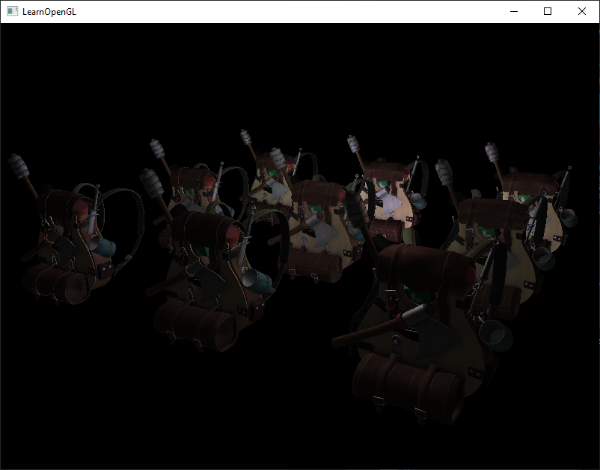
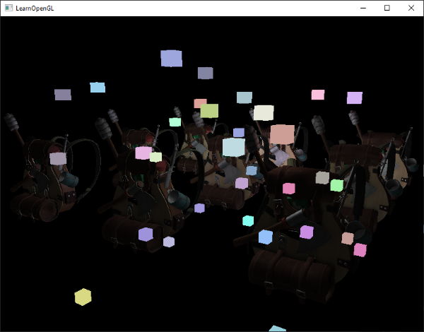
However, these rendered cubes do not take any of the stored geometry depth of the deferred renderer into account and are, as a result, always rendered on top of the previously rendered objects; this isn’t the result we were looking for.
然而,这些立方体在被渲染的时候没有考虑延迟渲染器存储的任何几何深度,因此始终渲染在先前渲染的对象之上,这不是我们想要的结果。
What we need to do, is first copy the depth information stored in the geometry pass into the default framebuffer’s depth buffer and only then render the light cubes. This way the light cubes’ fragments are only rendered when on top of the previously rendered geometry.
我们需要做的是,首先将存储在几何通道中的深度信息复制到默认帧缓冲的深度缓冲中,然后才渲染光源立方体。这样,光源立方体的片段仅在先前渲染的几何体之上时才会被渲染。
We can copy the content of a framebuffer to the content of another framebuffer with the help of glBlitFramebuffer, a function we also used in the anti-aliasing chapter to resolve multisampled framebuffers. The glBlitFramebuffer function allows us to copy a user-defined region of a framebuffer to a user-defined region of another framebuffer.
我们可以借助 glBlitFramebuffer 将一个帧缓冲的内容复制到另一个帧缓冲中,我们在抗锯齿一章中也使用了这个函数来求得多重采样帧缓冲。glBlitFramebuffer 函数允许我们将一个帧缓冲的用户定义区域复制到另一个帧缓冲的用户定义区域。
We stored the depth of all the objects rendered in the deferred geometry pass in the gBuffer FBO. If we were to copy the content of its depth buffer to the depth buffer of the default framebuffer, the light cubes would then render as if all of the scene’s geometry was rendered with forward rendering. As briefly explained in the anti-aliasing chapter, we have to specify a framebuffer as the read framebuffer and similarly specify a framebuffer as the write framebuffer:
我们将延迟几何通道中渲染的所有对象的深度存储在 gBuffer FBO 中。如果我们将其深度缓冲的内容复制到默认帧缓冲的深度缓冲中,然后渲染光源立方体,这样就好像场景的所有几何体都是使用正向渲染方法渲染的一样。正如在抗锯齿一章中简要解释的那样,我们必须指定一个帧缓冲作为读帧缓冲,同样地将一个帧缓冲指定为写帧缓冲:
1
2
3
4
5
6
7
glBindFramebuffer(GL_READ_FRAMEBUFFER, gBuffer);
glBindFramebuffer(GL_DRAW_FRAMEBUFFER, 0); // write to default framebuffer
glBlitFramebuffer(
  0, 0, SCR_WIDTH, SCR_HEIGHT, 0, 0, SCR_WIDTH, SCR_HEIGHT, GL_DEPTH_BUFFER_BIT, GL_NEAREST
);
glBindFramebuffer(GL_FRAMEBUFFER, 0);
[...]
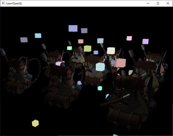
Here we copy the entire read framebuffer’s depth buffer content to the default framebuffer’s depth buffer; this can similarly be done for color buffers and stencil buffers. If we then render the light cubes, the cubes indeed render correctly over the scene’s geometry:
在这里,我们将整个读帧缓冲的深度缓冲内容复制到默认帧缓冲的深度缓冲中;这同样可以用于颜色缓冲和模板缓冲。随后我们再次渲染光源立方体,立方体确实被正确渲染在场景的几何体之上了:
You can find the full source code of the demo here.
你可以在此处找到示例的完整源代码。
With this approach we can easily combine deferred shading with forward shading. This is great as we can now still apply blending and render objects that require special shader effects, something that isn’t possible in a pure deferred rendering context.
通过这种方法,可以轻松地将延迟着色与前向着色相结合,这很棒,使得我们依然可以应用混合效果和渲染需要特殊着色效果的对象,以及做一些在单纯的延迟渲染环境中不可能做到的事情。
A larger number of lights
What deferred rendering is often praised for, is its ability to render an enormous amount of light sources without a heavy cost on performance. Deferred rendering by itself doesn’t allow for a very large amount of light sources as we’d still have to calculate each fragment’s lighting component for each of the scene’s light sources. What makes a large amount of light sources possible is a very neat optimization we can apply to the deferred rendering pipeline: that of light volumes.
延迟渲染最值得称赞的是,它能够在不造成严重性能损失的情况下渲染拥有大量光源的场景。延迟渲染本身不允许使用非常大量的光源,因为它仍然需要计算每个片段的每个场景光源光照分量。为此我们应用了一个非常巧妙的优化:光体积,从而使大量光源在延迟渲染管线中应用成为可能。
Normally when we render a fragment in a large lit scene we’d calculate the contribution of each light source in a scene, regardless of their distance to the fragment. A large portion of these light sources will never reach the fragment, so why waste all these lighting computations?
通常,当我们在大型光照场景中渲染片段时,我们会计算场景中每个光源的贡献,而不管它们与片段的距离如何。而实际上很大一部分光源的光线是根本到不了这个片段的,那么为什么要浪费所有这些光照计算呢?
The idea behind light volumes is to calculate the radius, or volume, of a light source i.e. the area where its light is able to reach fragments. As most light sources use some form of attenuation, we can use that to calculate the maximum distance or radius their light is able to reach. We then only do the expensive lighting calculations if a fragment is inside one or more of these light volumes. This can save us a considerable amount of computation as we now only calculate lighting where it’s necessary.
光体积背后的想法是计算光源的影响半径或体积,即就是光能够到达片段的范围。由于大多数光源都遵循某种形式的衰减,我们可以用这种衰减函数来计算光源的光能够达到的最大距离或半径。然后,只有当片段位于一个或多个这些光体积内时,我们才会进行昂贵的光照计算。这会为我们节省一个可观的计算量,因为我们现在只计算必要的光照。
Calculating a light’s volume or radius
To obtain a light’s volume radius we have to solve the attenuation equation for when its light contribution becomes 0.0. For the attenuation function we’ll use the function introduced in the light casters chapter:
为了获得光的体积半径,我们必须求解其光强度变为 0.0 时的衰减方程。对于衰减函数,我们将使用投光物那一章中介绍的函数:
\[F_{light} = \frac{I}{K_c + K_l * d + k_q * d^2}\]What we want to do is solve this equation for when $F_{light}$ is 0.0. However, this equation will never exactly reach the value 0.0, so there won’t be a solution. What we can do however, is not solve the equation for 0.0, but solve it for a brightness value that is close to 0.0 but still perceived as dark. The brightness value of 5/256 would be acceptable for this chapter’s demo scene; divided by 256 as the default 8-bit framebuffer can only display that many intensities per component.
我们要做的是当 $F_{light}$ 等于 0.0 时求解这个方程中的 $d$ 。然而,这个方程永远不会真正等于 0.0,因此不会有解。所以,我们不会求表达式亮度值等于 0.0 时候的解,而是求靠近 0.0 时的解,这时候亮度仍然可以被看做是黑暗的。对于本章的示例场景,亮度值 5/256 是可以接受的,除以 256 是因为默认的 8 位帧颜色缓冲每个分量最大值就是 256。
由上面曲线可以看出,我们使用的衰减方程在光的可视范围内绝大部分距离外都是黑暗的,所以如果我们想要限制亮度为一个比 5/256 更暗的值,光体积就会变得非常大而且低效。只要在光体积边缘看不到突兀的截断就行。当然这还是依赖于场景类型的,一个较高的亮度阀值会致使生成更小的光体积,从而获得更高的效率,但它同样会产生一个明显的加工痕迹,就是光会在光体积边界看起来突然断掉。
The attenuation equation we have to solve becomes:
我们需要求解的衰减方程变为:
\[\frac{5}{256}=\frac{I_{max}}{Attenuation}\]Here $I_{max}$ is the light source’s brightest color component. We use a light source’s brightest color component as solving the equation for a light’s brightest intensity value best reflects the ideal light volume radius.
这里 $I_{max}$ 是光源最亮的颜色分量,$Attenuation$ 是 $K_c + K_l * d + K_q * d^2$。我们使用光源最亮的颜色分量,是因为求解光源最亮强度值的方程最能反映理想的光体积半径。
From here on we continue solving the equation:
从这里开始,我们继续求解方程:
\[\frac{5}{256} * Attenuation = I_{max}\] \[5 * Attenuation = I_{max} * 256\] \[Attenuation = I_{max} * \frac{256}{5}\] \[K_c + K_l * d + K_q * d^2 = I_{max} * \frac{256}{5}\] \[K_c + K_l * d + K_q * d^2 - I_{max} * \frac{256}{5} = 0\] \[K_q * d^2 + K_l * d + (K_c - I_{max} * \frac{256}{5}) = 0\]The last equation is an equation of the form $ax^2+bx+c=0$ , which we can solve using the quadratic equation:
最后一个方程是 $ax^2+bx+c=0$ 形式的方程,我们可以使用二次方程求根公式求解:
\[d = \frac{-K_l + \sqrt{K_l^2 - 4*K_q*(K_c - I_{max} * \frac{256}{5})}}{2 * K_q}\]This gives us a general equation that allows us to calculate $d$ i.e. the light volume’s radius for the light source given a constant, linear, and quadratic parameter:
这给了我们一个一般方程,在已知常数项、一次线性参数项和二次参数项的情况下,允许我们计算光源的光体积半径 $d$:
1
2
3
4
5
6
7
float constant  = 1.0;
float linear    = 0.7;
float quadratic = 1.8;
float lightMax  = std::fmaxf(std::fmaxf(lightColor.r, lightColor.g), lightColor.b);
float radius    =
  (-linear +  std::sqrtf(linear * linear - 4 * quadratic * (constant - (256.0 / 5.0) * lightMax)))
  / (2 * quadratic);
We calculate this radius for each light source of the scene and use it to only calculate lighting for that light source if a fragment is inside the light source’s volume. Below is the updated lighting pass fragment shader that takes the calculated light volumes into account. Note that this approach is merely done for teaching purposes and not viable in a practical setting as we’ll soon discuss:
我们计算出场景中每个光源的体积半径,并仅当片段在光源的体积内时,才计算光源对片段的光照。下面是更新后的光照通道片段着色器,它把计算出的光体积考虑在内了。请注意,这种方法只用于教学目的,在实际生产环境中不可行,我们很快就会讨论为什么:
1
2
3
4
5
6
7
8
9
10
11
12
13
14
15
16
17
18
19
struct Light {
    [...]
    float Radius;
};

void main()
{
    [...]
    for(int i = 0; i < NR_LIGHTS; ++i)
    {
        // calculate distance between light source and current fragment
        float distance = length(lights[i].Position - FragPos);
        if(distance < lights[i].Radius)
        {
            // do expensive lighting
            [...]
        }
    }
}
The results are exactly the same as before, but this time each light only calculates lighting for the light sources in which volume it resides.
结果与之前完全相同,但这次每个光源只计算其光源体积内片段的光照。
You can find the final source code of the demo here.
你可以在此处找到示例的最终源代码。
How we really use light volumes
The fragment shader shown above doesn’t really work in practice and only illustrates how we can sort of use a light’s volume to reduce lighting calculations. The reality is that your GPU and GLSL are pretty bad at optimizing loops and branches. The reason for this is that shader execution on the GPU is highly parallel and most architectures have a requirement that for large collection of threads they need to run the exact same shader code for it to be efficient. This often means that a shader is run that executes all branches of an if statement to ensure the shader runs are the same for that group of threads, making our previous radius check optimization completely useless; we’d still calculate lighting for all light sources!
上面的片段着色器在实践中并不能真正起到提高性能的作用,它只说明了理论上如何利用光源的体积来减少光照计算。现实情况是,你的 GPU 和 GLSL 在循环和分支上优化非常糟糕。原因是 GPU 上的着色器执行是高度并行的,而且绝大多数架构都要求大量线程必须运行完全相同的着色器代码才能提高效率。这通常意味着着色器运行时会执行 if 语句的所有分支,以确保该组线程的着色器运行相同,这使得我们之前的半径检查优化完全无用:我们仍会计算所有光源的光照!
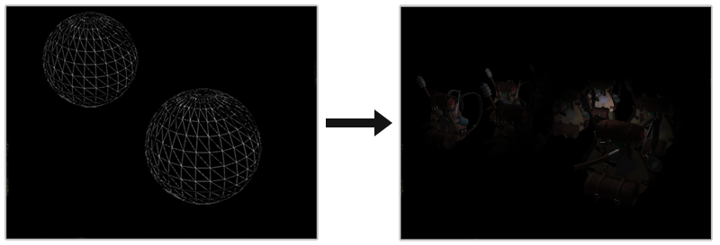
The appropriate approach to using light volumes is to render actual spheres, scaled by the light volume radius. The centers of these spheres are positioned at the light source’s position, and as it is scaled by the light volume radius the sphere exactly encompasses the light’s visible volume. This is where the trick comes in: we use the deferred lighting shader for rendering the spheres. As a rendered sphere produces fragment shader invocations that exactly match the pixels the light source affects, we only render the relevant pixels and skip all other pixels. The image below illustrates this:
使用光体积更好的方法是渲染按光体积半径缩放的实际球体。这些球体的中心位于光源的位置上,当它按光体积半径缩放时,正好包含了光源的可见范围体。这就是技巧所在:我们使用延迟光照着色器来渲染球体。由于渲染球体时光栅化后产生的屏幕像素区域与光源影响的屏幕像素区域完全一致,因此我们将会跳过所有其他像素只渲染相关像素(现在是一个一个的在光源位置渲染体积球,而非之前渲染一整个填充屏幕的四边形)。下图说明了这一点:
This is done for each light source in the scene, and the resulting fragments are additively blended together. The result is then the exact same scene as before, but this time rendering only the relevant fragments per light source. This effectively reduces the computations from nr_objects * nr_lights to nr_objects + nr_lights, which makes it incredibly efficient in scenes with a large number of lights. This approach is what makes deferred rendering so suitable for rendering a large number of lights.
对场景中的每个光源都这样做,然后将生成的片段相加混合在一起。结果就是与之前完全相同的场景,但这次只渲染每个光源的相关片段。这就有效地将计算量从 nr_objects * nr_lights 减少到 nr_objects + nr_lights,因此在有大量光源的场景中效率惊人。正是这种方法使得延迟渲染非常适合渲染大量光源。
当场景中存在环境光时,先绘制填充屏幕四边形,计算出只有环境光下的场景可见片段光照,得到场景环境光纹理。再绘制代表光源的体积球,计算出场景中光源影响的可见片段光照,得到场景漫反射高光纹理。最后将场景环境光纹理与漫反射高光纹理相加,就得到与之前完全相同的最终光照场景。假设较光源而言,物体可以被光源照射到的那面称为正面,无法被照射到的那面称为背面,当场景物体可见片段处于光源体积内,片段法线与光源光线方向相反时,说明片段可以被光源照射到,位于正面,片段法线与光源光线方向相同时,说明片段无法被光源照射到,位于背面。
There is still an issue with this approach: face culling should be enabled (otherwise we’d render a light’s effect twice) and when it is enabled the user may enter a light source’s volume after which the volume isn’t rendered anymore (due to back-face culling), removing the light source’s influence; we can solve that by only rendering the spheres’ back faces.
这种方法仍然存在一个问题:应该启用面剔除(否则我们会渲染光源的效果两次)。当启用背面剔除时,摄像机在移动进入到光源的体积内部后,该体积背面不再被渲染(由于背面剔除),这时体积内场景物体上就没有了这个光源的光照效果,我们可以通过只渲染球体的背面来解决这个问题。
Rendering light volumes does take its toll on performance, and while it is generally much faster than normal deferred shading for rendering a large number of lights, there’s still more we can optimize. Two other popular (and more efficient) extensions on top of deferred shading exist called deferred lighting and tile-based deferred shading. These are even more efficient at rendering large amounts of light and also allow for relatively efficient MSAA.
渲染光源确实会对性能造成影响,虽然到这一步后渲染大量光源时,比普通的延迟着色快了许多,但我们仍有很多可以优化的地方。在延迟着色的基础上,还有另外两种流行的(更高效的)扩展,即延迟光照和基于瓦片的延迟着色。这两种扩展在渲染大量光线时效率更高,而且还能实现相对高效的 MSAA。
Deferred rendering vs forward rendering
By itself (without light volumes), deferred shading is a nice optimization as each pixel only runs a single fragment shader, compared to forward rendering where we’d often run the fragment shader multiple times per pixel. Deferred rendering does come with a few disadvantages though: a large memory overhead, no MSAA, and blending still has to be done with forward rendering.
延迟着色本身(在没有光源体积情况下)是一项很好的优化,因为每个像素只运行一个片段着色器,而在前向渲染中,每个像素往往要多次运行片段着色器。不过,延迟渲染也有一些缺点:内存开销大,没有 MSAA,而且仍需使用前向渲染进行混合。
When you have a small scene and not too many lights, deferred rendering is not necessarily faster and sometimes even slower as the overhead then outweighs the benefits of deferred rendering. In more complex scenes, deferred rendering quickly becomes a significant optimization; especially with the more advanced optimization extensions. In addition, some render effects (especially post-processing effects) become cheaper on a deferred render pipeline as a lot of scene inputs are already available from the g-buffer.
当您的场景很小且光源不多时,延迟渲染不一定更快,有时甚至更慢,因为额外使用延迟渲染花费的开销会超过其带来的好处。在更复杂的场景中,延迟渲染很快成为了一项重要的优化;尤其是使用更高级的优化扩展。此外,某些渲染效果(尤其是后期处理效果)在延迟渲染管道上的成本会更低,因为很多场景输入已经可以从 g-buffer 中获得。
As a final note I’d like to mention that basically all effects that can be accomplished with forward rendering can also be implemented in a deferred rendering context; this often only requires a small translation step. For instance, if we want to use normal mapping in a deferred renderer, we’d change the geometry pass shaders to output a world-space normal extracted from a normal map (using a TBN matrix) instead of the surface normal; the lighting calculations in the lighting pass don’t need to change at all. And if you want parallax mapping to work, you’d want to first displace the texture coordinates in the geometry pass before sampling an object’s diffuse, specular, and normal textures. Once you understand the idea behind deferred rendering, it’s not too difficult to get creative.
最后,我想提一下,基本上所有可以通过前向渲染实现的效果也可以在延迟渲染上下文中实现;这通常只需要一小步的转换。例如,如果我们想在延迟渲染器中使用法线贴图,我们会更改几何通道着色器以输出从法线贴图(使用 TBN 矩阵)提取的世界空间法线,而不是表面法线;光照通道中的光照计算根本不需要更改。如果想让视差贴图发挥作用,则需要先变换几何通道中的纹理坐标,然后再对对象的漫反射、镜面反射和法线纹理进行采样。一旦你理解了延迟渲染背后的理念,就不难发挥创意了。
